Combustion is the burning of an air-fuel mixture to provide energy. It requires the presence of air, fuel, and a heat source to ignite the air-fuel mixture. In the internal combustion engine that powers automobiles and trucks the combustion happens inside the engine utilzing a fuel like gasoline, diesel fuel, or natural gas.
ASVAB Auto Information Study Guide
| Branch | All |
| Description | |
| Subtests | Automotive Information |
Automotive Information
- 103 Questions
- 103 Flash Cards
Engine Fundamentals
Components 22 17
Internal Combustion
Engine Block
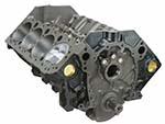
The engine (or cylinder) block is the large casing that contains the cylinders and many of the internal components of the engine.
Cylinders
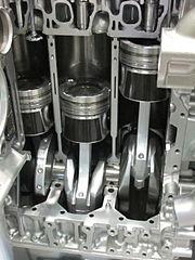
Cylinders act as a guide for the pistons that translate the heat energy of combustion into the mechanical energy necessary to move a vehicle. Piston rings seal the piston to the cylinder to contain combustion gases and also regulate the oil distribution between the piston and cylinder wall. A cylinder head closes in the top of the cylinder forming the combustion chamber which is sealed by a head gasket (head). The head provides space for air and fuel intake valves, exhaust valves, and mounts for spark plugs and fuel injectors.
Combustion Chamber
The combustion chamber is located in the cylinder head and contains the combustion of the air-fuel mixture. This mixture is delivered by an intake valve and the waste gases from combustion are removed from the combustion chamber by the exhaust valve.
Connecting Rod
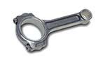
A connecting rod employs a wrist pin to link each piston to the engine's crankshaft.
Crankshaft
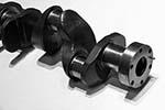
The crankshaft converts the reciprocating motion of the piston into the rotational motion that's used to power the vehicle and its components.
Camshaft
The camshaft is linked to the crankshaft through a timing belt and regulates the opening and closing of the intake and exhaust valves in each cylinder in time with the motion of the piston. An engine designated OverHead Camshaft (OHC) locates the camshaft in the cylinder head. An engine with Double OverHead Camshaft (DOHC) has two camshafts, one to regulate the intake valves and one to regulate the exhaust valves.
Cylinder Arrangement
Cylinder number and arrangement depends on the purpose of the engine. Smaller (four and six cylinder) engines in front-wheel drive vehicles often use an inline design which orients cylinders vertically over the crankshaft and aligns them in a row. Other common orientations are a horizontal/opposed design which places cylinders flat facing each other with the crankshaft between them and a V-type design common in six and eight cylinder engines that features one cylinder head per block of cylinders oriented at a 60 to 90 degree angle to each other with the crankshaft at the bottom of the V.
Stroke Cycle 7 5
Intake Stroke
The four-stroke piston cycle of internal combustion engines starts with the piston at top of the cylinder head (top dead center or TDC) during the intake stroke. The piston moves downward in the cylinder creating a vacuum that pulls an air-fuel mix into the combustion chamber through the now open intake valve.
Compression Stroke
During the compression stroke, both intake and exhaust valves are closed as the piston begins moving back up from the bottom of the cylinder (bottom dead center or BDC). This compresses the air-fuel mixture in the combustion chamber which also makes it hotter.
Power Stroke
During the power stroke, just before the piston reaches top dead center, the spark plug fires and ignites the compressed air-fuel mixture. The resulting expansion due to combustion pushes the piston back down the cylinder toward bottom dead center.
Exhaust Stroke
During the exhaust stroke, just before the piston reaches bottom dead center the exhaust valve opens. The resulting gases from combustion are then pushed out through the exhaust valve as the piston travels up the cylinder to top dead center, completing stroke four of the four-stroke piston cycle.
Operation 16 8
Firing Order
The stroke cycle of an engine is governed by the crankshaft which serves to regulate the firing order of the cylinders. All cylinders are not on the same stroke at the same time and correct firing order is important to balance engine operation and minimize vibrations. A common firing order for four-cylinder engines is 1-3-4-2 which indicates that cylinders 1 and 3 fire (power stroke)together and cylinders 4 and 2 fire together.
Air-Fuel Mixture
The stoichiometric ratio defines the proper ratio of air to fuel necessary so that an engine burns all fuel with no excess air. For gasoline fuel, the stoichiometric ratio is about 14.7:1 or for every one gram of fuel, 14.7 grams of air are required. Too much air results in a lean air-fuel mixture that burns more slowly and hotter while too much fuel results in a rich mixture that burns quicker and cooler.
Ignition Timing
Ignition timing defines the point in time at the end of the compression stroke that the spark plug fires. Measured in number of degrees before top dead center (BTDC), the exact point that the spark plugs initiate combustion varies depending on the speed of the engine. The timing is advanced (the spark plugs fire a few more degrees BTDC) when the engine is running faster and retarded when it's running slower.
Combustion
Normal combustion in an engine is initiated by a spark plug and results in the complete burning of the air-fuel mixture. If combustion is initiated by a source other than the spark plug, by a hot spot in the cylinder or combustion chamber for example, pre-ignition results. Detonation results if the air-fuel mixture explodes instead of burning. Detonation can cause extremes in pressure in the combustion chamber leading to engine damage.
Engine Systems
Cooling System 9 7
Coolant
Modern car engines are cooled by liquid which circulates through the engine block and cylinder heads absorbing excess heat. This liquid is made up of half water and half antifreeze (commonly, ethylene glycol) which both keeps the water from freezing at low temperatures and raises its boiling point making heat transfer more efficient.
Water Pump
The water pump is driven by a belt connected to the crankshaft and ensures that coolant moves through the engine and radiator.
Water Jacket
A water jacket is a coolant-filled casing that allows heat transfer from the engine block and cylinder heads to the liquid coolant.
Thermostat
The thermostat controls coolant (and, through it, engine) temperature by regulating the flow of coolant through the radiator. A bypass tube allows coolant to bypass the radiator and flow back into the water pump when its temperature is low enough that the thermostat is closed.
Radiator
The radiator is responsible for tranferring heat from the coolant to the outside air. Radiator hoses transfer coolant to and from the engine to the radiator and a radiator cap maintains pressure in the cooling system to increase the boiling point of the coolant mixture and thus allow it to absorb more heat.
Lubrication System 5 7
Purpose
The lubrication system lubricates engine components by putting an oil film between them to reduce friction and smooth engine operation, cools by absorbing heat from engine parts, seals the pistons and cylinders to contain combustion, cleans contaminants, and quiets engine noise.
Oil Viscosity
The primary component of the lubrication system is engine oil. Engines require oil blends with different thickness (viscosity) and additives depending on their operating conditions. Viscosity is rated using the format XW-XX with the number preceding the W (winter) rating the oil’s viscosity at 0 ℉ (-17.8 ℃) and the XX indicating viscosity at 100 ℃.
Oil Pump
The oil pump is driven by the camshaft and is responsible for pumping oil through the oil galleries (passages) that run throughout the engine. It also contains the oil filter and a pressure relief valve which prevents excessive pressure from building up in the lubrication system.
Oil Pan
The oil pan contains the engine oil reservoir of from four to six quarts of oil and feeds the oil pump through the oil pickup tube. An oil strainer floats at the top of the oil in the oil pan and screens debris from the oil before feeding it to the oil pump.
Fuel System 5 6
Fuel Injector
The fuel injector sprays fuel into the air stream that's being fed into the cylinder head via the intake valve. The timing and amount of fuel are regulated by the powertrain control module (PCM) which is the main computer that controls engine and transmission functions.
Electric Fuel Pump
The electric fuel pump feeds pressurized fuel through a fuel filter to the fuel injectors via the fuel rail manifold. The fuel rail contains the fuel pressure regulator which ensures that the fuel injectors receive fuel at a consistent and known rate. Excess fuel bled off by the pressure regulator returns to the fuel tank through the fuel return line.
Intake Manifold
The intake manifold distributes outside air to the intake ports on the cylinder heads. The intake air filter removes any airborne contaminants before the air enters the engine.
Ignition System 7 7
Battery
The battery supplies the power necessary to start the engine when the ignition switch is is turned on.
Ignition Coil
The ignition coil is a high-voltage transformer made up of two coils of wire. The primary coil winding is the low-voltage winding and has relatively few turns of heavy wire. The secondary coil winding is the high-voltage winding that surrounds the primary and is made up of thousands of turns of fine wire. Current flows from the battery through the primary coil winding which creates a changing magnetic field inside the secondary coil. This induces a very high-voltage current in the secondary coil which it feeds to the distributor.
Distributor
The distributor is driven by the engine's camshaft and is responsible for timing the spark and distributing it to the correct cylinder. The distributor cap contains a rotor that connects the ignition coil (and its high voltage) to the proper cylinder at the proper point in the stroke cycle.
Spark Plugs
Spark plugs receive current from the distributor and use it to spark combustion in the combustion chamber of a cylinder.
Exhaust System 3 5
Exhaust Manifolds
The cast iron exhaust manifolds collect engine exhaust gas from multiple cylinder exhaust valves and deliver it to the exhaust pipe. Exhaust manifolds can be generic or specially tuned (header pipes) to the engine. Header pipes deliver higher performance but are more expensive and less durable.
Catalytic Converter
The catalytic converter converts pollutants in exhaust gas into less pollutant substances like carbon dioxide and water.
Muffler
The muffler follows the catalytic converter and absorbs sound to help quiet load exhaust. It is followed by the exhaust pipe which is the final exit point for exhaust gas from the vehicle.
Electrical and Computer Systems
Electrical System Components 5 6
Battery
The lead-acid battery is the core of the electrical system, providing current to the ignition system to start the engine as well as delivering supplemental current when the alternator can't handle high electrical system loads and acting as an electrical reservoir for excessive current.
Solenoid
The cylindrical solenoid is a relay that safely connects the high amperage battery to the starter motor when the ignition key is turned. This current then allows the engine to turn at a high enough speed to start.
Alternator
Once the engine is running, the alternator provides electrical current to recharge the battery and power the electrical system. The alternator is driven by the engine's crankshaft and produces alternating current (AC) which is then fed through a rectifier bridge to convert it to the direct current (DC) required by the electrical system. A voltage regulator controls the output of the alternator to maintain a consistent voltage (approx. 14.5 volts) in the electrical system regardless of load.
Lighting
The lighting system consists of interior lights, instrument panel lighting, headlights, and taillights. Like household electrical circuits, the vehicle's lighting system is protected from current spikes by fuses and circuit breakers.
Computer System Components 3 3
Sensors
Sensors provide the data necessary for the vehicle's computer to make decisions and monitor everything from simple vehicle information like tire pressure to complexities like the chemical content of an engine's exhaust.
Powertrain Control Module
The main computer or powertrain control module (PCM) uses pre-programmed software to analyze the input received from sensors and produce output signals to adjust vehicle performance and operation. (Engine control unit (ECU) is another name for the PCM.)
Actuators
Actuators receive signals from the powertrain control module and carry out adjustments needed based on the data the PCM received from the sensors.
Operational Systems
Drive Train 7 11
Transmission
The transmission provides the appropriate power to vehicle wheels to maintain a given speed. The engine and the transmission have to be disconnected to shift gears and a manual transmission requires the driver to manually manage this disconnection (using a clutch) and to manually shift gears. An automatic transmission is essentially an automatic gear shifter and handles this process without driver input.
Transaxle
A differential is designed to drive a pair of wheels while allowing them to rotate at different speeds. A transaxle is a transmission that incorporates the differential in one package. Most front-wheel drive cars use a transaxle while rear-wheel drive cars use a transmission and separate differential connected via a drive shaft. The differential is incorporated into the drive axle which splits engine power delivered by the drive shaft between the two drive wheels. All-wheel drive cars typically use a transaxle that includes an output shaft to the rear differential.
Half Shaft
A half shaft is a drive axle that extends from a transaxle or differential to one of the drive wheels. There are two half shafts per drive axle, one for each wheel, each doing "half" the job.
CV Joints
Constant velocity (CV) joints are located at both ends of a half shaft and their purpose is to transfer the torque from the transmission to the drive wheels at a constant speed while accomodating the up and down movement of the suspension. The inner CV joint connects the shaft to the transmission and the outer CV joint connects the shaft to the wheel.
Universal Joints
Like CV joints, universal joints (U-joints) are located at each end of a drive shaft and allow the shaft to operate at a variable angle with the item it is driving. Universal joints perform the same basic function as CV joints but CV joints have a wider range of operation.
Transfer Case
The transfer case splits engine power between the front and rear axles of four-wheel drive vehicles.
Suspension and Steering System 7 13
Independent Suspension
Most modern cars use an independent suspension system on the front wheels. This setup allows each of the wheels on an axle to move independently in response to road level variations. Independent suspension offers much better handling and stability when compared to a rigid axle suspension at the cost of being structurally weaker and more costly to maintain.
Springs
Suspension springs are made with wide gap coils of rigid steel cable and both hold the vehicle chassis up off the ground and absorb energy from wheel movement making for a smoother ride.
Shock Absorbers
Because a compressed spring will extend violently, shock absorbers must be used to dampen the spring’s compression and extension cycles. Struts combine the spring and shock into one unit
Control Arms
Control arms (upper and lower) connect a vehicle's suspension to the frame. The connection to the wheels is through ball joints which allow the control arms to turn and move up and down simultaneously. The frame connection uses bushings.
Steering Linkage
The steering linkage is a system of pivots and connecting parts between the steering gear and the control arms. The steering linkage transfers the motion of the steering gear output shaft to the steering arms that turn the wheels.
Wheel Hub
The wheel hub is the mounting point for the wheel and tire assembly. The wheel hub can rotate while being held stable by the steering knuckle which applies the motion of the control arms to the wheels.
Braking System 7 8
Master Cylinder
The master (brake) cylinder converts pressure on the brake pedal to hydraulic pressure in the brake lines.
Fluid Reservoir
The fluid reservoir stores the brake fluid that the master cylinder uses to maintain hydraulic pressure.
Brakes
Brakes utlize friction to slow vehicle tires. Drum brakes employ a cast iron drum that roates with the vehicle axle. When hydraulic pressure is applied to the brake assemblies at the wheels, internal pistons expand and push brake shoes outward into contact with the brake drum slowing the rotation of the axle. More powerful disc brakes operate by pinching a rotating disc betweeen two brake pads and allow for a larger surface area to contact the disc, provide more force, and are more easily cooled.
Power Brakes
Power brakes multiply the force a driver applies to the brake pedal using a vacuum booster connected to the engine intake manifold. This provides for much higher hydraulic pressure in the braking system than could be generated by the driver alone. Antilock brakes (ABS) use speed sensors and adjust the brake pressure at each wheel to prevent skidding and allow the driver more steering control in slippery conditions.